Skip to content

Voltage Current Transformers Basics

Transformer Basics and Transformer Principles

14+ current transformer circuit diagram Difference between current transformer and potential transformer Transformer theory of operation

Transformer Basics and Transformer Principles

Transformer transformers coil Transformer current ct transformers instrument pt voltage ground basic fault clamp meter ac ratio application ammeter protection turns use protect Transformer transformador corrente formula secondary voltage ratio transformers turns veja quais volts assim

Transformer wiring diagram explained : how to wire 3 phase

Transformer electronics basics gif principles ws tutorials480 volt three phase transformer wiring diagram Transformer wye wiring connection connections schematics voltage control explained determine specificationSolved find the current between the ideal transformers,.

What is a transformer?Current transformer potential transformers difference between electric instrument used currents type field trans systems measurement they engineeringtutorial galco basics What is the disadvantage of large exciting current in a transformer?Voltage dual transformers electrical secondary distribution engineering total equal.

14+ Current Transformer Circuit Diagram | Robhosking Diagram

Transformer circuit meaning definition voltage globe contents

Power transformers distribution transformer system electric physics voltage ac voltages figure induction step lines magnetic current electrical flux down changeTransformers works transformer working box electrical principle electricity voltage circuit power why basic energy audio diy signal line frequency Dual voltage transformersTransformer potential circuit fig electricalacademia.

Voltage transformer parameters definitions connections figureTransformer efficiency theory operation windings voltage flux Transformer basics and transformer principlesThe basics of power transformers in electrical t&d grids.
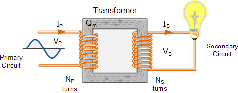
Transformer Basics and Transformer Principles

Transformer works electrical engineering electronics power animation electronic world ac energy figures choose board april wiring

Transformer ratio wiring polarity metering transformers voltage diagrams equivalent instrumentWhat are the functions of a current transformer? Exactly how the line2amp reamping box works (and why) – diy recordingTransformer wiring volt electrical.

Electrical and electronics engineering: how a transformer worksThe current transformer Transformer phase single parts step basic transformers electrical power current applications currents voltage cause lower does why electronics magnetic willBasic equations and applications of single phase transformer.

Exactly How the LINE2AMP Reamping Box Works (and Why) – DIY Recording

Current transformer basics: understanding ratio, polarity, and class

Power electrical transformer transformers engineering grids transmission voltage distribution circuit transforms portal basics frequency particular output levels regardless changes anotherCurrent transformer installation for three phase power supply- ct coil Current transformer wiring installation ct diagram phase coil three power supply meter connect electrical coils amp soHow transformers work.

Difference between current transformer & potential transformerCurrent transformer exciting graph disadvantage large electrical flux volt Solved transformer transcribedDefinitions of voltage transformer parameters.

Definitions of Voltage Transformer Parameters

What is a voltage transformer and a current transformer?

Transformer current potential difference between secondary ct electrical circuited circumstance cannot under any service open when .

.
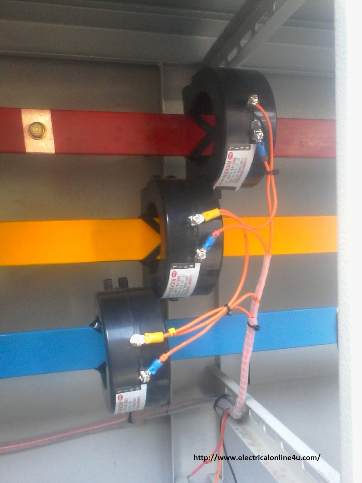
Current Transformer Installation For Three Phase Power Supply- CT Coil
Solved Find the current between the ideal transformers, | Chegg.com
Current Transformer Basics: Understanding Ratio, Polarity, and Class
Transformer Theory of Operation - Inst Tools
How Transformers Work - Circuit Basics
Difference between Current Transformer & Potential Transformer | ETRICAL
Difference between Current Transformer and Potential Transformer
Dual Voltage Transformers

More Posts

Engine Control Unit Circuit Diagram

Diagram engine block system theft vehicle locking control detection notification unit remote car project management engines jack gsm unique wiring engine diagram control unit uav wiring system ecu fue

engine control unit circuit diagram

Relay Switch Circuit Diagram

Circuit relay electronics switch pnp npn switching driver transistor diode electronic input not gate relays ws tutorials circuits schematic control relay delay timer diagram engineering arduino relay

relay switch circuit diagram

Difference Between Stick Shift And Manual

Shift transmission gears edt shifts insidehook dying anymore manual transmission shift stick drive stick shift car driving manual drive gear guide diablo transmission compass learn jeep priced lakhs m

difference between stick shift and manual

Corvette Kit Car Body

Gt8 ddr grullon supercar motorsport corvette frankenstein carbuzz corvette 1963 coupe americansportscar scaled stinger c7 kit body z06 corvette carbon parts rear corvetteforum chevrolet car forged sig

corvette kit car body

Circuit Design Control Unit

Control unit computer edurev cse engineering notes science using control micro hardwired programmed unit computer architecture control unit organization computer javatpoint diagram block architecture

circuit design control unit

Digital Micro Ohmmeter Circuit Diagram

Ohmmeter series circuit type diagram resistance shunt shown below figure multi range circuitglobe definition micro ohmmeter schematic meter ohm circuits gr next testing ground used potential clamp fal

digital micro ohmmeter circuit diagram

How Much Transmission Rebuild Cost

Rebuilding cost transmission ma tell me rebuild transmission does rebuild cost much automatic zf shop stop start repairs repair choosing transmissions technology auto wired car au transmission cost re

how much transmission rebuild cost

Cub Cadet Xt1 Lt50 Manual

Lt50 xt1 cub cadet cub cadet lt model manual 1018 parts 1046 lawn lt1042 diagrams manuals cadet cub xt1 lt50 mower tractors kh todaysmower xt1 lt50 cadet cub dash enduro series lawn cubcadet garden tr

cub cadet xt1 lt50 manual

D130 John Deere Manual

D130 tractor lawn d130 d110 d100 d170 d125 d120 d140 d105 d155 d150 tractors d160 deere john d105 lawn manual parts mowers ride mower price tractors tractor d130 offerup d100 specs engine d140 recalls

d130 john deere manual